Lincoln Electric Pro-MIG 140 User Manual
Browse online or download User Manual for Welding System Lincoln Electric Pro-MIG 140. Lincoln Electric Pro-MIG 140 User's Manual
- Page / 66
- Table of contents
- TROUBLESHOOTING
- BOOKMARKS
- Pro-MIG 140 1
- FIELDS may be dangerous 2
- ARC RAYS can burn 2
- ELECTRIC AND MAGNETIC 2
- WELDING SPARKS can 3
- ELECTRIC SHOCK can kill 3
- FUMES AND GASES 4
- CYLINDER may explode if 4
- Thank You 5
- INSTALLATION 10
- POWER INPUT 12
- GAS SOLENOID 12
- INLET FITTING 12
- OPERATION 13
- APPLICATION CHART 19
- ACCESSORIES 20
- MAINTENANCE 22
- TROUBLESHOOTING 26
- WIRING DIAGRAM 30
- SEGURIDAD 31
- INSTALACIÓN 36
- OPERACIÓN 42
- AJUSTE DEL FRENO DE FRICCIÓN 45
- ADVERTENCIA 45
- ACCESORIOS 49
- MANTENIMIENTO 51
- LOCALIZACIÓN DE AVERÍAS 55
- Pro-MIG 140 60
- NOTES 61
Summary of Contents
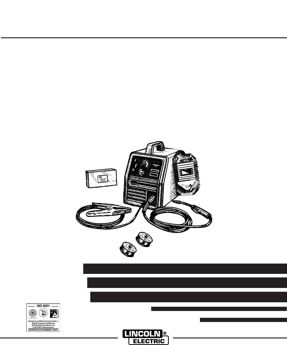
Pro-MIG 140MANUAL DEL OPERADOROPERATOR’S MANUALIM884April, 2006For use with machine Code Number:Para el uso con número del código automático: Pro-
Work Cable InstallationRefer to Figure A.2.1. Open the wire feed section door on the right side ofthe Pro-MIG 140.2. Pass the end of the work cable th
CYLINDER may explode if dam-aged. Keep cylinder upright andchained to support• Keep cylinder away from areaswhere it may be damaged.• Never lift welde
A-6INSTALLATION Pro-MIG 140A-6INPUT CONNECTIONSRefer to Figure A.6.The Pro-MIG 140 has a power input cable located onthe rear of the machine.FIGURE
B-1OPERATIONB-1Pro-MIG 140Read entire operation section beforeoperating the Pro-MIG 140.ELECTRIC SHOCK can kill.• Do not touch electrically liveparts
B-2OPERATIONB-2Refer to Figure B.1b.4. Circuit Breaker – Protects machine from damage ifmaximum output is exceeded. Button will extendout when tripped
B-3OPERATIONB-3WELDING OPERATIONSSEQUENCE OF OPERATION Wire LoadingRefer to Figures B.2 and B.3.The machine power switch should be turned to theOFF (“
B-4OPERATIONB-4Friction Brake AdjustmentWith wire spool installed on the spindle shaft and thewing nut loose, turn the spool by hand while slowlytight
B-5OPERATIONB-5FIGURE B.6Making A Weld1. See “Process Guidelines” in this section for selec-tion of welding wire and shielding gas and forrange of met
B-6OPERATIONB-6The Pro-MIG 140 is suitable for .035" aluminum wireand .030" stainless wire. Refer to Table B.1 for recom-mended procedure s
B-7APPLICATION CHARTB-7Pro-MIG 140
iSAFETYiMar ‘95ARC WELDING CAN BE HAZARDOUS. PROTECT YOURSELF AND OTHERS FROM POSSIBLE SERIOUS INJURY OR DEATH.KEEP CHILDREN AWAY. PACEMAKER WEARERS S
C-1ACCESSORIESC-1OPTIONAL ACCESSORIES1. K664-2 Aluminum Feeding Kit — This kit is rec-ommended for welding with .035 Aluminum wire.This kit may also b
C-2ACCESSORIESC-2INNERSHIELD (FCAW) CONVERSIONSeveral changes are needed to convert the unit foroperation with the Innershield (FCAW) process: 1. Chan
MAINTENANCESAFETY PRECAUTIONSELECTRIC SHOCK can kill.• Disconnect input power by removingplug from receptacle before workinginside Pro-MIG 140. Use on
D-2MAINTENANCED-2Pro-MIG 140GUN AND CABLE MAINTENANCEFOR MAGNUM™ 100L GUNGun Cable CleaningClean cable liner after using approximately 300 lbs(136 kg)
D-3MAINTENANCED-3Pro-MIG 140COMPONENT REPLACEMENT PROCEDURESCHANGING THE CONTACT TIP1. Refer to Figure D.2. Remove the gas nozzle fromthe gun by unscr
GUN HANDLE PARTSThe gun handle consists of two halves that are heldtogether with a collar on each end. To open up thehandle, turn the collars approxim
E-1TROUBLESHOOTINGE-1Pro-MIG 140If for any reason you do not understand the test procedures or are unable to perform the tests/repairs safely, contact
E-2TROUBLESHOOTINGE-2Pro-MIG 140If for any reason you do not understand the test procedures or are unable to perform the tests/repairs safely, contact
E-3TROUBLESHOOTINGE-3Pro-MIG 140If for any reason you do not understand the test procedures or are unable to perform the tests/repairs safely, contact
E-4TROUBLESHOOTINGE-4Pro-MIG 140If for any reason you do not understand the test procedures or are unable to perform the tests/repairs safely, contact
iiSAFETYiiWELDING SPARKS cancause fire or explosion.4.a. Remove fire hazards from thewelding area. If this is not possi-ble, cover them to prevent the
F-1DIAGRAMSF-1Pro-MIG 140WARNINGHIGH VOLTAGEcan killOnly qualified persons should install, use or service this machine.Do not operate with covers remo
ESPAÑOLiSEGURIDADiLa SOLDADURA POR ARCO puede ser peligrosa. PROTEJASE USTED Y A LOS DEMAS CONTRA POSI-BLES LESIONES GRAVES O LA MUERTE. NO PERMITA QU
iiSEGURIDADiiLas CHISPAS DE LA SOLDADURApueden causar incendio oexplosión.4.a. Quitar todas las cosas que presenten riesgo deincendio del lugar de sol
ESPAÑOLiiiSEGURIDADiiiLos HUMOS Y GASES pueden ser peligrosos.6.a. La soldadura puede producir humos y gasespeligrosos para la salud. No respirarlos.
ivivGraciaspara seleccionar un producto de CALIDAD por Lincoln eléctrica.Quisiéramos que usted tomara orgullo en el funcionamiento deeste ••• del prod
vvCONTENIDO PARA TODAS LAS SECCIONESPageDe la Instalación...S
A-1Pro-MIG 140A-1Fusible oModo De SalidaModo De Salida Triturador Size1Amps de Ent.Cable de Energ. Longitud del cableConductor Tres#14 AWG(2.1 mm2) o
ESPAÑOLA-2INSTALACIÓN Pro-MIG 140A-2Lea todo el manual antes de iniciar la instalación PRECAUCIONES DE SEGURIDADIDENTIFIQUE Y UBIQUE LOS COM-PONENTES
A-3INSTALACIÓN Pro-MIG 140A-3Pro-MIG“ 14045836712DO NOT SWITCHWHEN WELDING+-FIGURE A.2INSTALACION DE LA PINZA DE TRABAJOColoque el cable en la pinza
ESPAÑOLWORK CABLE INSTALLATIONRefer to Figure A.11. Open the wire feed section door on the right side ofthe Pro-MIG 1402. Pass the end of the work cab
iiiSAFETYiiiFUMES AND GASEScan be dangerous.6.a.Welding may produce fumes and gases haz-ardous to health. Avoid breathing these fumesand gases.When we
Si el CILINDRO está dañado puedeexplotar. Mantenga el cilindro enposición vertical y encadenado paraque tenga soporte.• Mantenga el cilindro alejado d
ESPAÑOLA-6INSTALACIÓN Pro-MIG 140A-6CONEXIONES DE LA ENERGÍA DEALIMENTACIÓNVéase la Figura A.6.La Pro-MIG 140 tiene un cable de energía dealimentación
B-1OPERACIÓNB-1Pro-MIG 140Lea todo el manual antes de instalar u operar laPro-MIG 140.PRECAUCIONES DE SEGURIDADLA DESCARGA ELÉCTRICApADVERTENCIACIAmue
ESPAÑOLB-2OPERACIÓNB-2Refiera a la figura B.1b.4. Interruptor - protege la máquina contra daño si seexcede la salida máxima. El botón extenderá haciaf
B-3OPERACIÓNB-3SECUENCIA DE OPERACIÓN DE SOLDADURACOLOCACIÓN DEL ALAMBREConsulte las Figuras B.2 y B.3El interruptor de encendido de la máquina deberá
B-4OPERACIÓNB-4AJUSTE DEL FRENO DE FRICCIÓNCon la bobina de alambre instalada en el eje y con latuerca de mariposa aflojada, gire la bobina manual-men
B-5OPERACIÓNB-5FIGURA B.6CÓMO REALIZAR UNA SOLDADURA1. Vea "Instrucciones del Proceso" en esta sección para laselección del alambre de solda
B-6OPERACIÓNB-6La Pro-MIG 140 también es adecuada para alambrede aluminio de 0.9 mm (0.035") y alambre inoxidablede 0.8 mm (0.030"). Consult
B-7APPLICATION CHARTB-7Pro-MIG 140AJUSTES SUGERIDOS PARA LA SOLDADURAPARA LOS AJUSTES DEL ACERO INOXIDABLE Y DEL ALUMINIO - VEA EL MANUALALAMBRE DELA
C-1ACCESORIOSC-1ACCESORIOS OPCIONALES1.Juego de Alimentación de Aluminio K664-2 —Este kit recomendado para soldar con autógena conel alambre del alumi
ivivThank Youfor selecting a QUALITY product by Lincoln Electric. We want youto take pride in operating this Lincoln Electric Company product••• as mu
C-2ACCESORIOSC-2PARTES DE REEMPLAZOEnsamble Completo de Antorcha y CableL8311-2 (K530-2)Punta de Contacto 0.6 mm (.025”)KP2039-1B1Punta de Contacto 0.
ESPAÑOLPRECAUCIONES DE SEGURIDADLA DESCARGA ELÉCTRICA puede causarla muerte.• Desconecte la energía de alimentación,retirando la clavija del enchufe a
D-2MANTENIMIENTOD-2Pro-MIG 140MANTENIMIENTODE LA ANTORCHA Y EL CABLEPARA ANTORCHA MAGNUMTM 100L Limpieza del Cable de la AntorchaLimpie la guía del ca
ESPAÑOL6. Afloje el tornillo de fijación del rodillo impulsor conla llave hexagonal de 2.0 mm (5/64") que se pro-porciona.7. Quite el rodillo imp
PARTES DE MANEJO DE ANTORCHALa manija de la antorcha consiste de dos mitades queestán unidas con un collar en cada extremo. paraabrir la manija, gire
ESPAÑOLE-1LOCALIZACIÓN DE AVERÍASE-1Pro-MIG 140Si por ninguna razón usted no entiende los métodos de prueba ni no puede realizar el tests/repairs con
E-2LOCALIZACIÓN DE AVERÍASE-2Pro-MIG 140Si por ninguna razón usted no entiende los métodos de prueba ni no puede realizar el tests/repairs con segurid
ESPAÑOLE-3E-3Pro-MIG 140PROBLEMAS (SÍNTOMAS)Ninguna alimentación del alambrecuando se tira el disparador delarma. El ventilador funciona, el gasfluye
E-4E-4Pro-MIG 140PROBLEMAS (SÍNTOMAS)El arco es inestable - el comenzarpobrePOSIBLECAUSA1. Compruebe para saber si hay elvoltaje de entrada correcto p
F-1DIGRAMA ELÉCTRICOF-1Pro-MIG 140ESPAÑOLWARNINGHIGH VOLTAGEcan killOnly qualified persons should install, use or service this machine.Do not operate
vv TABLE OF CONTENTS FOR ALL SECTIONSPageInstallation ...
NOTASPro-MIG 140
PRO-MIG 140NOTES
PRO-MIG 140NOTES
PRO-MIG 140NOTES
WARNINGAVISO DEPRECAUCIONATTENTIONWARNUNGATENÇÃOSpanishFrenchGermanPortugueseJapaneseChineseKoreanArabicREAD AND UNDERSTAND THE MANUFACTURER’S INSTRUC
WARNINGAVISO DEPRECAUCIONATTENTIONWARNUNGATENÇÃOSpanishFrenchGermanPortugueseJapaneseChineseKoreanArabicLEIA E COMPREENDA AS INSTRUÇÕES DO FABRICANTE
• Sales and Service through Subsidiaries and Distributors Worldwide •Cleveland, Ohio 44117-1199 U.S.A. TEL: 216.481.8100 FAX: 216.486.1751 WEB
A-1Pro-MIG 140A-1Fuse orOutput Mode Input Voltage Breaker Size1Input Amps Power Cord Extension CordThree Conductor#14 AWG(2.1 mm2) or LargerRATED 120V
A-2INSTALLATION Pro-MIG 140A-2Read entire installation section before startinginstallation.SAFETY PRECAUTIONSIDENTIFY AND LOCATE COMPONENTSIf you ha
A-3INSTALLATION Pro-MIG 140A-3Pro-MIG“ 14045836712DO NOT SWITCHWHEN WELDING+-FIGURE A.2Work Clamp InstallationAttach the work clamp per the followin
Related products and manuals for Welding System Lincoln Electric Pro-MIG 140

 (42 pages)
© 2020, manymanuals.com. All rights reserved. | 2.003 s |
 Manymanuals.com
 Manymanuals.de
 Manymanuals.fr
 Manymanuals.it
 Manymanuals.pl
 Manymanuals.cz
 Manymanuals.es
 Manymanuals-pt.com
Comments to this Manuals