Lincoln-electric POWER ARC 5000 User Manual
Browse online or download User Manual for Tools Lincoln-electric POWER ARC 5000. Lincoln Electric POWER ARC 5000 User Manual
- Page / 50
- Table of contents
- TROUBLESHOOTING
- BOOKMARKS
- POWER ARC 1
- FOR ENGINE 2
- ELECTRIC AND 2
- MAGNETIC FIELDS 2
- ARC RAYS can burn 3
- ELECTRIC SHOCK can 3
- FUMES AND GASES 3
- PRÉCAUTIONS DE SÛRETÉ 5
- PRÉCAUTIONS DE SÛRETÉ POUR 5
- LES MACHINES À SOUDER À 5
- TRANSFORMATEUR ET À 5
- REDRESSEUR 5
- Thank You 6
- TABLE OF CONTENTS 7
- INSTALLATION 10
- OPERATION 17
- ACCESSORIES 36
- MAINTENANCE 37
- TROUBLESHOOTING 42
- DIAGRAMS 45
- Lincoln Welding School 47
Summary of Contents
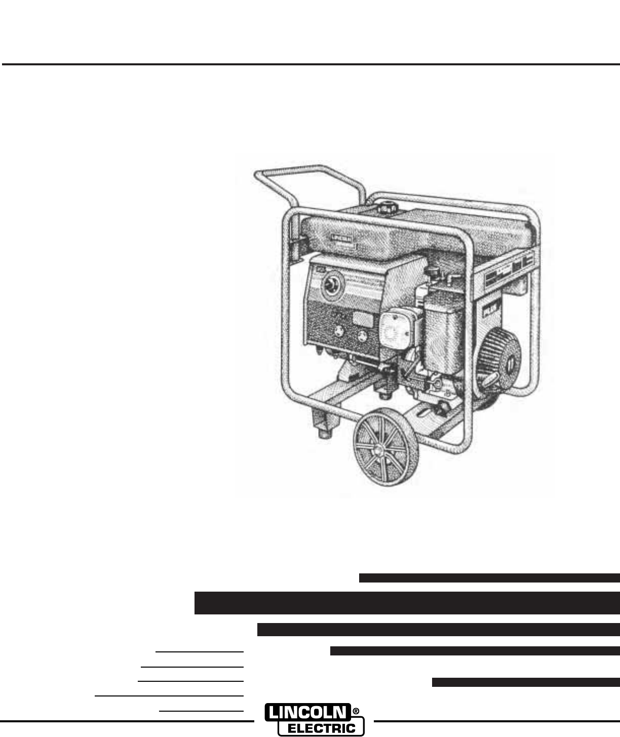
OPERATOR’S MANUALSafety Depends on YouLincoln arc welding and cuttingequipment is designed and builtwith safety in mind. However, youroverall safety c
A-3INSTALLATION POWER ARC 5000A-3STACKINGPOWER ARC 5000 machines CANNOT be stacked.TILTINGPlace the machine on a secure, level surface whenev-er you
A-4INSTALLATION POWER ARC 5000A-4Assembly of Wheels and Handle to theTube FrameTools Required - Two 9/16 wrenches or sockets, 3/8 wrenchor socket an
A-5INSTALLATION POWER ARC 5000A-5PRE-OPERATION ENGINE SERVICERead and understand the information about the gasolineengine in the OPERATION and MAINT
TABLE A.1RECOMMENDED WELDING CABLE SIZE AND LENGTHTOTAL COMBINED LENGTH OF ELECTRODE ANDWORK CABLESCable Size for 150 amp/Cable Length 40% Duty Cycle0
A-7INSTALLATION POWER ARC 5000A-7Cable InstallationInstall the welding cables to your POWER ARC 5000as follows. See Figure A.3 for the location of
A-8INSTALLATION POWER ARC 5000A-8POWER CORD CONNECTIONS TO TWIST-LOCK PLUGSRefer to the appropriate diagram above for properconnection of power cord
TABLE A.2ELECTRICAL DEVICE USE WITH THE POWER ARC 5000.Type Common Electrical Devices Possible ConcernsResistive Heaters, toasters, incandescent NONE
B-1OPERATIONB-1OPERATING INSTRUCTIONSRead and understand this entire section before oper-ating your POWER ARC 5000.SAFETY INSTRUCTIONSDo not attempt t
B-2OPERATIONB-2RECOMMENDED APPLICATIONSOPERATIONAL FEATURES AND CONTROLSThe POWER ARC 5000 was designed for simplicity.Therefore, it has very few oper
B-3OPERATIONB-3GENERATOR/WELDER CONTROLSSee Figure B.1 for the location of the following fea-tures:1. CURRENT CONTROL DIAL: Adjusts continuouscurrent
FOR ENGINEpowered equipment.1.a. Turn the engine off before troubleshooting and maintenancework unless the maintenance work requires it to be running.
B-4OPERATIONB-4GASOLINE ENGINE CONTROLSSee Figure B.2 for the location of the following fea-tures:1. FUEL SHUTOFF VALVE: Stops the flow of gaso-line f
B-5OPERATIONB-5ENGINE OPERATIONDO NOT RUN THE ENGINE AT EXCESSIVE SPEEDS.The maximum allowable high idle speed for thePOWER ARC 5000 is 3750 RPM, no l
B-6OPERATIONB-64. Pull the cord rapidly.5. If the engine does not start, open the chokeslightly (move lever toward the “RUN” position)and pull the sta
B-7OPERATIONB-7GENERATOR OPERATIONBe sure that any electrical equipment plugged intothe generator’s AC power receptacles can withstanda +5%-15% voltag
B-8OPERATIONB-8POWER ARC 5000NOTES:Wattages listed are approximate. Check your equipment for actual wattage.Equipment with unusually high *START-UP W
B-9OPERATIONB-9WELDING OPERATIONGENERAL INFORMATIONDo not touch electrically live parts or elec-trodes with your skin or wet clothing.Arc Rays can bur
TABLE B.4WELDING APPLICATIONS/ELECTRODE SELECTION GUIDEAWS ELECTRODE TYPE SIZE MATERIAL INITIAL RANGECLASS THICKNESS SETTINGE6011 FLEETWELD 180 3/32
B-11OPERATIONB-11POWER ARC 5000The Power-Arc provides excellent weld output charac-teristics when used in combination with Lincoln ACelectrodes. Other
B-12OPERATIONB-12POWER ARC 5000The POWER ARC 5000 has a voltage output of up to62 volts which can shock.The electric arc is made between the work and
B-13OPERATIONB-13POWER ARC 50001. The Correct Welding PositionIllustrated is the correct welding position forright-handed people. (For left-handed pe
iiSAFETYiiARC RAYS can burn.4.a. Use a shield with the proper filter and coverplates to protect your eyes from sparks andthe rays of the arc when weld
B-14OPERATIONB-14POWER ARC 5000PRACTICEThe best way of getting practice in the four skills thatenable you to maintain:1. Correct Welding Position.2.
B-15OPERATIONB-15POWER ARC 5000Now weld the two plates together. Weld from left toright (if right-handed). Point the electrode down in hegap between
B-16OPERATIONB-16POWER ARC 5000Vertical-Up WeldingThe problem, when welding vertical-up, is to put themolten metal where it is wanted and make it stay
B-17OPERATIONB-17POWER ARC 5000Overhead WeldingVarious techniques are used for overhead welding.However, in the interest of simplicity for the inexper
B-18OPERATIONB-18POWER ARC 50004. The bead should be put on with a weaving motion,and it should be 1/2-3/4” (12.7-19.0mm) wide. Donot let the arc blo
B-19OPERATIONB-19POWER ARC 5000This group includes electrodes which have a moder-ately forceful arc and deposit rates between those ofthe out-of-posit
C-1ACCESSORIESC-1OPTIONS/ACCESSORIESLINCOLN ELECTRIC ACCESSORIESThe following options/accessories are available foryour POWER ARC 5000 from your local
D-1MAINTENANCED-1SAFETY PRECAUTIONS• Have qualified personnel do all maintenance andtroubleshooting work.• Turn the engine off before working inside t
D-2MAINTENANCED-2CLEAN AIR FILTER PRE-CLEANERDo not use petroleum solvents such as kerosene toclean the air pre-cleaner. They may cause deteriora-tio
TABLE D.1ENGINE MAINTENANCE SCHEDULEMaintenance Every 5 Hours 25 Hours 50 Hours 100 HoursOperation or Daily or Yearly or Yearly or Yearly 100-300 Hour
FOR ELECTRICALLYpowered equipment.8.a. Turn off input power using the disconnectswitch at the fuse box before working onthe equipment.8.b. Install equ
D-4MAINTENANCED-4POWER ARC 5000GENERATOR/WELDER MAINTENANCESTORAGE: Store the POWER ARC 5000 in clean,dry, protected areas.CLEANING: Blow out the gene
D-5MAINTENANCED-5POWER ARC 50001 . OUTPUT PANEL ASSEMBLY2. CONTROL BOX ASSEMBLY 3. ENGINE AND CRADLE ASSEMBLY4. STATOR AND ROTOR ASSEMBLYFIGURE D.7
E-1TROUBLESHOOTINGE-1POWER ARC 5000Observe all Safety Guidelines detailed throughout this manualIf for any reason you do not understand the test proce
E-2TROUBLESHOOTINGE-2POWER ARC 5000Observe all Safety Guidelines detailed throughout this manualIf for any reason you do not understand the test proce
E-3TROUBLESHOOTINGE-3POWER ARC 5000Observe all Safety Guidelines detailed throughout this manualIf for any reason you do not understand the test proce
F-1DIAGRAMSF-1POWER ARC 5000NOTE: This diagram is for reference only. It may not be accurate for all machines covered by this manual. The specific
F-2DIAGRAMSF-2POWER ARC 5000R20.0026.50M180536-28-96POWER ARC 500029.31POWER ARC 5000 - DIMENSION PRINT
Now Available...12th EditionThe Procedure Handbook of Arc WeldingWith over 500,000 copies of previous editions publishedsince 1933, the Procedure Hand
WARNINGAVISO DEPRECAUCIONATTENTIONWARNUNGATENÇÃOSpanishFrenchGermanPortugueseJapaneseChineseKoreanArabicREAD AND UNDERSTAND THE MANUFACTURER’S INSTRUC
WARNINGAVISO DEPRECAUCIONATTENTIONWARNUNGATENÇÃOSpanishFrenchGermanPortugueseJapaneseChineseKoreanArabicLEIA E COMPREENDA AS INSTRUÇÕES DO FABRICANTE
ivSAFETYivPRÉCAUTIONS DE SÛRETÉPour votre propre protection lire et observer toutes les instruc-tions et les précautions de sûreté specifiques qui par
• Sales and Service through Subsidiaries and Distributors Worldwide •Cleveland, Ohio 44117-1199 U.S.A. TEL: 216.481.8100 FAX: 216.486.1751 WEB
Thank Youfor selecting a QUALITY product by Lincoln Electric. We want youto take pride in operating this Lincoln Electric Company product••• as much p
PageSafety...
A-1INSTALLATION POWER ARC 5000A-1TECHNICAL SPECIFICATIONS - POWER ARC 5000INPUT - GASOLINE ENGINEManufacturer Description Speed Displacement Ignitio
A-2INSTALLATION POWER ARC 5000A-2Read this entire installation section before youstart installation.SAFETY PRECAUTIONSDo not attempt to use this equ
Related products and manuals for Tools Lincoln-electric POWER ARC 5000


 (29 pages)
(34 pages)
(36 pages)
(166 pages)
(29 pages)
(34 pages)
(36 pages)
(166 pages)
© 2020, manymanuals.com. All rights reserved. | 1.195 s |
 Manymanuals.com
 Manymanuals.de
 Manymanuals.fr
 Manymanuals.it
 Manymanuals.pl
 Manymanuals.cz
 Manymanuals.es
 Manymanuals-pt.com
Comments to this Manuals